Will a 5 Stage Filtration System Protect Agains Low Water Pressure
 What is the perfect water pressure level for my RO?
Most revers osmosis membranes are designed to work with threescore PSI or higher water pressure level, where they are tested to yield a stable rejection rate of at least 97.5%. If the h2o pressure feeding an RO system is less than that, the arrangement will produce less water and at a lower quality. Additionally, product is reduced whenever the water temperature is below 77 °F. Private well systems most commonly have pressurized storage tank and pump systems with 20/40 psi or 30/50 psi on/off pressure settings. In such cases an electric pressure boosting pump must be installed to provide adequate rejection of specific health-related contaminants in the feedwater, such equally nitrate or arsenic and others specified by the Us EPA or local regulations.
What if I connect my ice maker?
RO water will produce cleaner ice cubes because of the purity of frozen water. So, connecting your RO to the ice maker makes a lot of sense. Still, new water ice makers crave 30-twoscore PSI incoming water pressure to part properly. Y'all may non have plenty pressure at the pressurized h2o tank since your RO cuts the line force per unit area by 30-35%.
How tin can I increase water pressure?
We will discuss several ways to boost the pressure coming out from your cold-water line to run the RO.
Boosting Pressure level Using a Permeate Pump

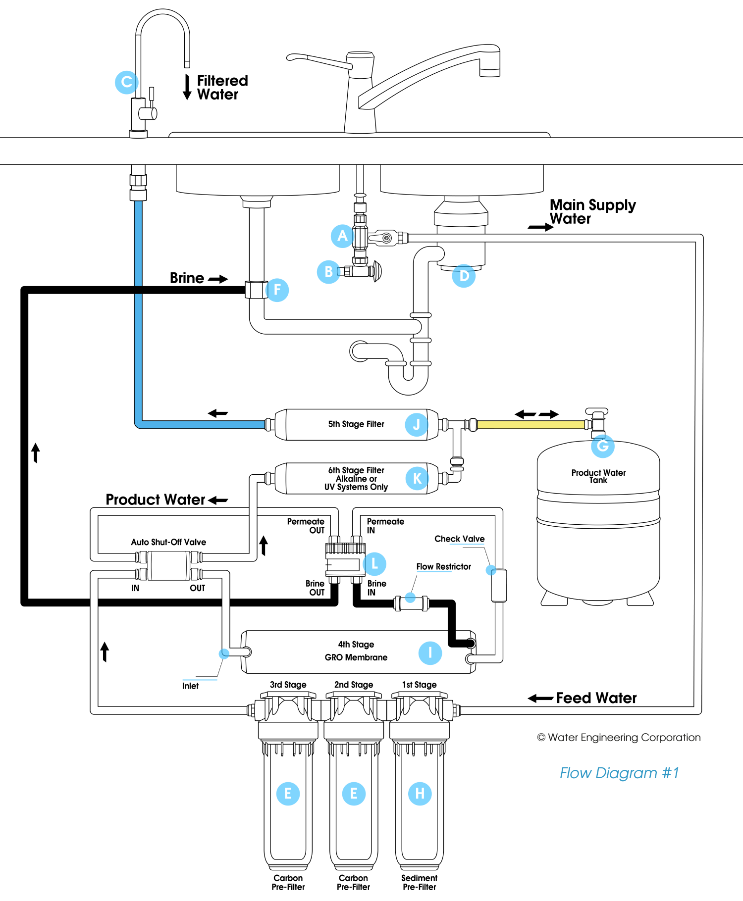
Permeate pumps use the energy of bleed water menstruum from opposite osmosis system as leverage to push the purified h2o into the property tank. Aquatec, the manufacturer of ERP-1000 permeate pump states that these pumps dramatically improve the efficiency of reverse osmosis h2o (RO) product, reducing wastewater by up to eighty%. Permeate pumps can easily be retrofitted to upgrade existing RO systems.

Menses Diagram #ane

Boosting Pressure using an Electrical Booster Pump

Adding an electrical booster pump increases the RO production charge per unit, boosts the pressure level tank storage book, rejects more contaminants and increases faucet catamenia rate even if the reverse osmosis membrane pressure rating is met past the water supply. Residnetial RO systems work with diaphragm booster pumps that volition typically increase the feed pressure upto 75-100 PSI.
Install the pump directly in the RO feed line (see diagrams below) following these guidelines.
- A sediment filter should always protect the pump big particulate matter in water. If the blueprint permits, install the pump between the sediment filter and carbon filter since carbon filters before the pump may become too restrictive of the water menstruum and starve the pump.
- Pumps must be mounted following suppliers recommendation. Mounting orientations such as pump vertical with head downwardly may encourage air-locking, leading to pressure loss.
- Mountain the high force per unit area switch (tank switch) every bit closest to the tank equally possible to avoid cycling of pump by reacting to the pressure level drib in the tubing when the drinking water faucet is opened.
- Catamenia of water through the pump is indicated by an pointer. Exist sure you insert the tubing correctly.
- If the boosted force per unit area is too high (typically >100 PSI), the RO fittings and housings can develop leaks. There is a top adjustment spiral on the pump head that tin can be used to lower the pressure.
What is the perfect water force per unit area for my RO?
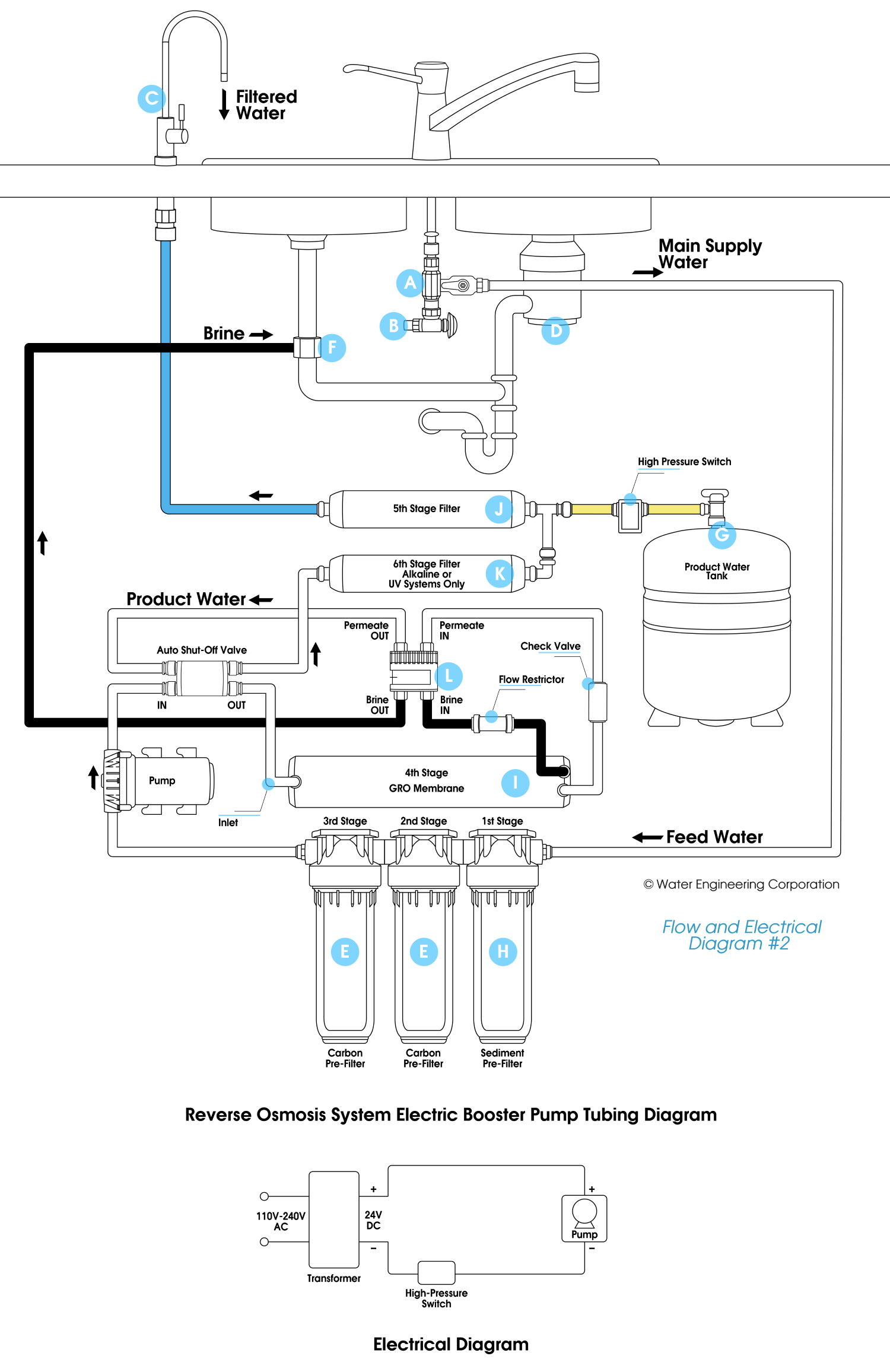
An electric booster pump kit such as FC-1400 can very efficienty heave the line pressure up to lxxx PSI. This elementary depression-cost setup is the most commonly used design in residential reverse osmosis industry. A differential pressure controlled automatic close off device (ASO valve) and a loftier-pressure switch controlls the pump and water flow into the membrane. When the tank pressure gets up to 60% of the incoming pressure level the valve internally closes off the inlet. This will build up pressure on the loftier-pressure switch.
FC-1400 kit includes a 1/four" quick connect ASO valve, pump, transformer and a high-pressure switch for RO systems upto fifty GPD.
FC-3800 kit includes a iii/8" quick connect ASO valve, pump, transformer and a high-pressure switch for RO systems upto 100 GPD.

Menstruation Diagram #2

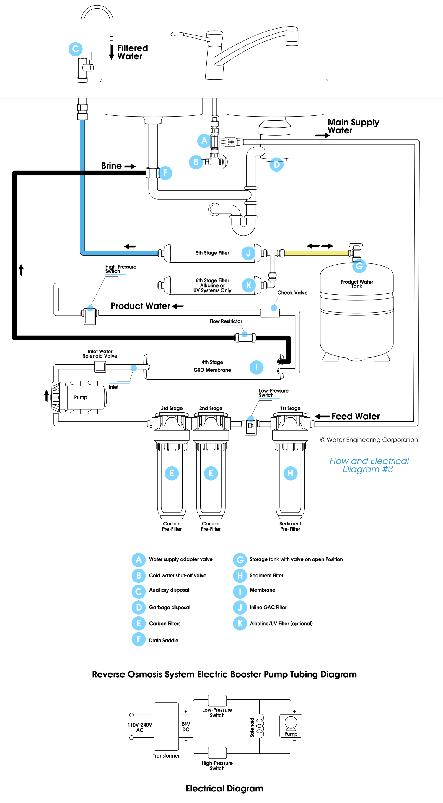
Internal Plumbing - Design 2 Using Solenoid
Nearly commercial reverse osmosis systems and high-end residential ro systems employ the following blueprint. Booster pump hither is controlled by 2 pressure switches. A low-pressure switch at the inlet (activated or conducting current around 5 PSI) makes certain the pump will not run dry. A high-pressure switch (deactivated at twoscore, 60 or lxxx PSI) cuts off power to the pump when the pressurized water storage tank has reached the capacity. A solenoid valve stops water supply to the membrane when the pump is off, preventing h2o running downwards the drain continuously. Wiring and plumbing diagrams below. ELCON-24 kit includes the solenoid, pump, transformer and high/low pressure switches.

Menses Diagram #3

Like shooting fish in a barrel External Plumbing - Blueprint 3
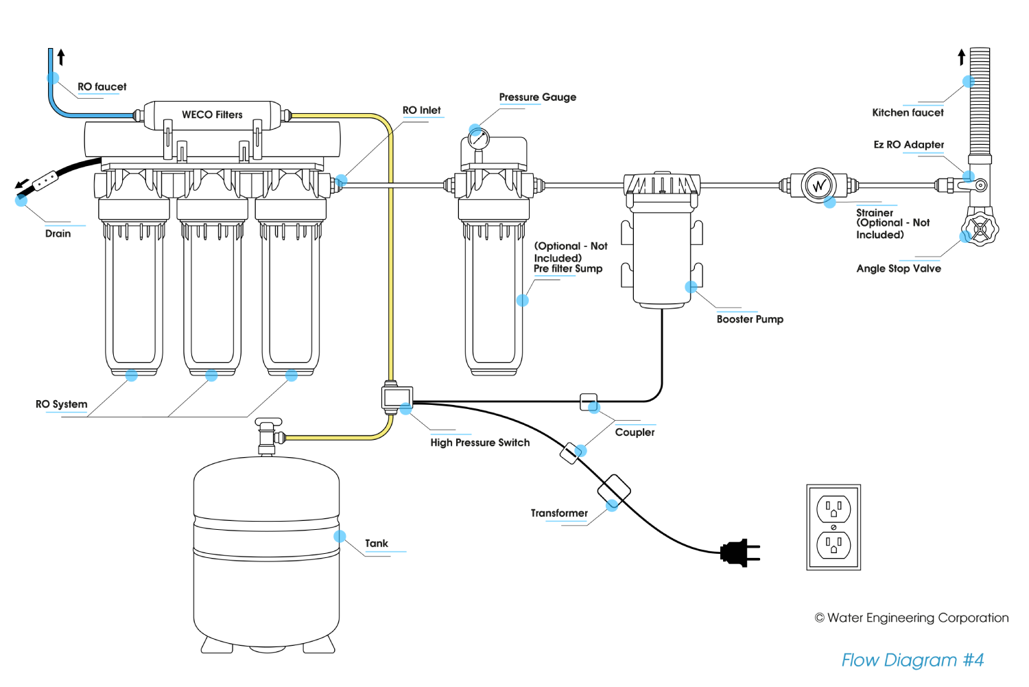
Blueprint below requires no internal plumbing modifications on your RO system. Merely mount the booster pump between the water supply and the RO. A high pressure level switch will mountain on the pressurized storage tank tubing. This force per unit area switch cuts off power to the pump when the water storage tank reaches 40 PSI (or rated pre set pressure of the switch).
Our economy pump retrofit kits ECON-50P utilize this blueprint. Premium retrofit kit GYC-1400 also includes a pressure gauge system with a pre-filter pressure stabilizer every bit well as a strainer to protect the pump from sediment. Video below illustrates installing of the premium kit.

Flow Diagram #4

burnhambotinquiered1951.blogspot.com
Source: https://www.wecofilters.com/blog/post/booster-pump-installation
0 Response to "Will a 5 Stage Filtration System Protect Agains Low Water Pressure"
Enregistrer un commentaire